"LogicWorks is an interactive circuit design tool intended for teaching and learning digitial logic." LogicWorks 5 is the newest version of LogicWorks. It is a program that we can use for designing and simulating circuits. This lab material will introduce you the basic features of LogicWorks and familiarize you with the program by stepping you through the construction of a simple circuit.
You start LogicWorks by clicking on the icon ![]() on the desk top or selecting it from the Microsoft Windows Start menu.
Once the tool is open, you will see the "Welcome to the LogicWorks" screen.
on the desk top or selecting it from the Microsoft Windows Start menu.
Once the tool is open, you will see the "Welcome to the LogicWorks" screen.
Select "Create a new circuit diagram" by clicking on the "Create" button. Then the following screen is displayed.
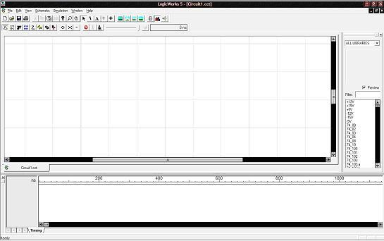
There are three primary window components in LogicWorks. They are Circuit Window, Timing Window, and the Parts Palette. Now let's look at each of them.
The circuit window is where you build your circuits. For example, you can select different parts from the Parts Palette and place the device in the circuit Window to build your circuits. The following is a screen capture of the circuit window with a sample circuit already drawn.
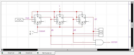
You can select any part of the circuit by left clicking on it, once selected, a right click can bring up a pop menu that displays the options for manipulating the selected component.
When a circuit is simulated, the Timing diagram window can be displayed to show signal values versus time. Only one Timing window can be displayed at any given time, and it gives waveforms generated by the current design. Closing the Timing window does not close the circuit design file. The following picture shows the corresponding timing window of the above example circuit.

Like the Circuit window, the intervals of the timing diagram can be selected by using click and drag the mouse over the desired interval. Once a section of the diagram is selected, right click brings up a pop menu with options that can be used to manipulate the Timing diagram.
Parts Palette is another very important part of LogicWorks interface. By default, it is located to the right of the Circuit Window. The location can be changed by holding down the left mouse button on the double stripped title bar near the top and dragging the window to the desired location. Usually, I would recommand that you keep it in the default location.

When you click on a device, it shows in the preview area. It is illustrated by the above picture. Parts Palette contains a group of parts libraries. You can choose a proper library and select a device to place in the Circuit Window to build your circuits.
In this section, you will build and test a circuit that implements the following Boolean equation:
	1.	Three AND gates with two inputs (AND-2)
        2.	Two OR gates with two inputs (OR-2)
        3.	A single NOT gate commonly called an inverter
        4.	Some wire to connect the gates
        5.	Three switches to provide a way to modify the input values for testing
        6.	A binary probe to show the results of the circuit
The first three components can be found in the "Simulation Gates.clf" library:
"Simulation Gates.clf" should now be displayed in the pull-down menu window of the Parts Window as shown in Fig. 1. The next portion of the Parts Window displays a list of the logic gates contained in this library. The scroll bar can be used to view them all. Put the desired devices on the schematic (The Circuit Design Window):
|
Fig. 1 |

Fig. 3 |
OR Gates:
|
NOT Gates (Inverters):
|

Fig. 4 |
	By single clicking on an item on the schematic (The Circuit Design Window)
	the device will be selected and highlighted.  While the device is selected,
	the Delete key will remove the item from the schematic.
	To move a device, point at it and hold down the left mouse button,
	then move the mouse to the desired location.  Release the mouse button.
Adding switches:
|

Fig. 5 |
Adding wires:
|

Fig. 6 |
Recall that we are trying to implement Z = AB + BC + AC'. To clarify your design and show its relation to the equation above, we will label the wires A, B, C, and Z.
Labeling wires:

Fig. 8 |

Fig. 7 |
Note: This process can also be done by clicking on the
buttone A on the top tool bar.  The mouse pointer then looks like a little pencil. Point this
pencil at one of the wires (remember only the red parts are wires,
if you click on a black part you are labeling a pin) and click on it.
A text box appears and you can type a name for the wire.
Hit Esc/Space to exit the name process.
The mouse pointer then looks like a little pencil. Point this
pencil at one of the wires (remember only the red parts are wires,
if you click on a black part you are labeling a pin) and click on it.
A text box appears and you can type a name for the wire.
Hit Esc/Space to exit the name process.
When you named these wires you should have noticed that in The Timing Window the names appeared. This will later show you the values of these three variables.

Fig. 9 |
|
Note: The wire will go around one corner for you, but you may have to stop in the middle of the schematic with one wire and then restart to go in another direction. Also, an intersection without a dot is simply two wires crossing without making a connection.

Fig. 10 |
|
Here is the Simulator Toolbar:

	For example,

	1.	Clicking on the <> or >< button can adjust the range
		of the time values to suit the display data.

	2.	Clicking on the Reset button can make the simulation
		restart at time 0.

	3.	Clicking on the Run button can start the simulation.
You may have noticed that in the Timing Window that there are small lines drawn like underscores for inputs A, B, and C. These are low because the switches are all set to the zero value.
	Notice that the A line in the Timing Window went up to a high
	level, indicating the value 1. Also notice that the Z output went high.
	This is because A is high and C' is high and according to the equation
	Z should be high with these input values.

To insert the text in the circuits window, click on the button A
in the design toolbar , then follow the following steps.
	1.	Position your pencil (cursor) at the desired location.
	2.	Type in the text
	3.	Change cursor to the pointer by clicking on the pointer
		in the toolbar or press the space bar or escape key.
	4.	Click on the text entered, then right click.
	5.	Select "Text Style" and then select the prefered options
		and press ok.
Look at the next picture, you can see the Equation of the circuit in the circuit design window.
To save or print your work, click the File menu and then select the proper option. The following picture illustrates the idea.
By now, you have learned plenty about LogicWorks, but there is much more to learn. Play around with it. If you think of a feature you would like to use, it probably exists. There are 8 copies of the LowgiWork 5 manul available in the RESERVED section in the main Library if you want to work through their tutorials or want to know more. You may ask me questions at lab time or at my office hours in CL119. If a lab requires new features, I will explain more within the lab.
|
Friday, 21-Aug-2020 15:27:45 CST |
|
| |
|
|
