CS405 Lab 2: Fundamental OpenGL Functions
Highlights of this lab:
This lab is an introduction to Fundamental OpenGL Functions
-
Overview of Device Contexts (DC), Rendering Contexts (RC) and Pixel
Formats
-
Basic OpenGL rendering primitives
Assignment:
After the lab lecture, you have one week to:
- Use the lab 1 "OpenGL" framework, and create your own scene
using OpenGL primitives
- Show the instructor your results in the scheduled lab time
On-line
OpenGL Manual
Seminar Notes
A. What is OpenGL?
-
OpenGL is an operating system and hardware platform independent
graphics library designed to be easily portable yet rapidly
executable.
B. Why is OpenGL used?
- OpenGL was originally developed by Silicon Graphics Inc.
(SGI) for
its workstations running under X-Windows. It rapidly became the
industrial standard for high-quality 3D graphics applications.
- Unlike Direct3D, which is only available on PC, Xbox and
Xbox 360,
OpenGL is available on a wide variety of hardware platforms and
operating systems including X-Windows (Linux, Irix, BSD, Solaris), Mac
OS X, Microsoft Windows 95, 98, 2000, NT, XP, and Vista. Variations
of it are used as the core graphics library for most game consoles,
including Nintendo DS, Game Cube, Wii, Playstation 1,2, and 3.
C. What are the basic steps to use OpenGL in a Windows
Program?
-
Getting a Device Context (DC) for the rendering location
- Selecting and setting a pixel format for the Device Context
- Creating a Rendering Context (RC) associated with the
Device Context
- Drawing using OpenGL commands
- Releasing the rendering context
- Release the device context
D. What is a DC?
- A DC is simply a data structure that keeps the state of the
current settings and route calls to the appropriate device.
E. What is an RC?
- An RC is a data structure that keeps the state variables
for OpenGL. It is also a portal through which OpenGL calls are
sent to the device.
- You can think of both DC and RC as a data structure
that keeps the state of the current settings and routes calls to the
proper
device.
F. Brief Introduction to Pixel
Format Data Structure
- Pixel formats are the translation between OpenGL calls
(such as an
OpenGL call to draw a pixel with an RGB triad value of [128,120,135])
and the rendering operation that Windows performs (the pixel might be
drawn with a translated RGB value of [128,128,128]). The selected
pixel format describes such things as how colors are displayed, the
depth of field resolution, and what additional capabilities are
supported by the rendering context you have created. The Windows
OpenGL has four functions that handle the pixel format.
 Pixel Format Function Description
------------------------------------------------------------------
ChoosePixelFormat() Obtains a DC's pixel format that's the
 closest match to a pixel format you've
	provided.

SetPixelFormat() Sets a DC's current pixel format to the
 pixel format index specified.

GetPixelFormat() Returns the pixel format index of a DC's
 current pixel format.

DescribePixelFormat() Given a DC and a pixel format index, fills
	a PIXELFORMATDESCRIPTOR data structure with
	the pixel format's properties.
The main properties of pixel format include:
-
Single or double buffering: Mainly for smooth animation.
- RGBA or color indexing: A color can be directly
specified by Red, Green,
and Blue values. Some video display controllers have limited frame
buffer
memory. For example, EGA supports 16 colors. Therefore, only 4 bits is
used to represent a pixel. This pixel value is used as the index into
a color map to find the associated RGB values for display.
- Drawing to a window or bitmap: When a drawing is sent
to a window, it will be
displayed in real-time on the screen. A bitmap is a canvas in the main
memory. The content in a bitmap may be displayed later by being copied
into
a window.
- Support of GDI (Window's Graphics Device Interface) or
OpenGL calls.
- Color depth: The number of bits per pixel in the frame
buffer.
- Z-axis depth: The number of bits per pixel in Z-buffer
that is used for
hidden surface removal.
The following structure can be found in the Windows include file
WINGDI.H:
typedef struct tagPIXELFORMATDISCRIPTOR
{
 WORD nsize;
 WORD nVersion;
 BYTE dwFlags;
 BYTE iPixelType;
 BYTE cColorBits;
 BYTE cRedBits;
 BYTE cRedShift;
 BYTE cGreenBits;
 BYTE cGreenShift;
 BYTE cBlueBits;
 BYTE cBlueShift;
 BYTE cAlphaBits;
 BYTE cAlphaShift;
 BYTE cAccumBits;
 BYTE cAccumRedBits;
 BYTE cAccumBlueBits;
 BYTE cAccumAlphaBits;
 BYTE cDepthBits;
 BYTE cStencilBits;
 BYTE cAuxBuffers;
 BYTE iLayerType;
 BYTE bReserved;
 DWORD dwLayerMask;
 DWORD dwVisisbleMask;
 DWORD dwDamageMask;
} PIXELFORMATDISCRIPTOR,
*PPIXELFORMATDISCRIPTOR,
FAR *LPPIXELFORMATDISCRIPTOR;
- You may refer to Chapter 2 of the reference book by Fosner
for
detailed description, and view lab 1's function
BOOL COpenGLView::SetupPixelFormat( ) in the file OpenGLView.cpp.
G. Basic Rendering Function
For the first part of the following discussion it may
be useful to try out the OpenGL
Shapes Demo — instructions.
 glBegin(GL_POINTS);
 glVertex2f(0.0f, 2.0f); //note 2D form
 glVertex2f(1.0f, 2.0f);
 glVertex2f(0.0f, -2.0f);
 glVertex2f(-1.0f, 0.0f);
 glEnd();
There are also other types of points. 3D vertex can be similarly drawn.
They are listed below:
	glVertex2d, glVertex2f, glVertex2i, glVertex2s,
 glVertex3d, glVertex3f, glVertex3i, glVertex3s,
 glVertex4d, glVertex4f, glVertex4i, glVertex4s,
 glVertex2dv, glVertex2fv, glVertex2iv, glVertex2sv,
 glVertex3dv, glVertex3fv, glVertex3iv, glVertex3sv,
 glVertex4dv, glVertex4fv, glVertex4iv, glVertex4sv
The postfix specifies the format of parameters used by each function:
- 2 means a 2D point x, y.
- 3 means a 3D point x, y, and z.
- 4 means a 3D point in homogeneous coordinates x, y, z,
and w.
[Homogeneous coordinates will be discussed in the lecture on Chapter
5.]
- d means double type.
- f means float type.
- i means integer type.
- s means short type.
- v means vector type.
- u[bsi] means unsigned version of that type
Example: using vector type parameter.
	double P1[2], P2[2], P3[2];

	/* set values to P1, P2, P3. */
	P1[0] = 1.5; P1[1] = -0.3;
	......

	glBegin(GL_POINTS);
	glVertex2dv(P1);
	glVertex2dv(P2);
	glVertex2dv(&P3[0]); /* This is equivalent. */
	glEnd();
Refer to online manual for details.
OpenGL lines
Three different line primitives can be created:
draws a line segment for each pair of vertices.
 draws a connected group of line segments from vertex v0
to vn connecting a line between each vertex and the
 next in the order given.
 similar to GL_LINE_STRIP, except it closes the line from
 vn to v0, defining a loop.

 glBegin(GL_LINE_LOOP); //make it a connected close line segment
 glVertex2f(0.0f, 2.0f); //note 2D form
 glVertex2f(1.0f, 2.0f);
 glVertex2f(0.0f, -2.0f);
 glVertex2f(-1.0f, 0.0f);
 glEnd();
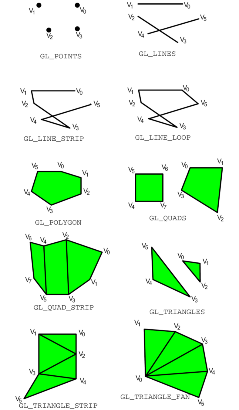
OpenGL polygons
The following code constructs a filled in parallelogram on
the x-y plane:
 glBegin(GL_POLYGON);
 glVertex2f(0.0f, 2.0f); //note 2D form
 glVertex2f(1.0f, 2.0f);
 glVertex2f(0.0f, -2.0f);
 glVertex2f(-1.0f, 0.0f);
 glEnd();
There are also other types of points.
3D vertex can be similarly drawn.
Refer to online manual.
The following draws a rectangle:
 glRectf(0f, 0f, 1f, 1f); // x0, y0, x1, y1: two opposite corners
	// of the rectangle.
it is the same as:
 glBegin(GL_QUADS);
	glVertex2f(0.0f, 0.0f); //note 2D form
	glVertex2f(1.0f, 0.0f);
	glVertex2f(1.0f, 1.0f);
	glVertex2f(0.0f, 1.0f);
 glEnd();
Specifying a color
glColor*( )
 For example, glColor3f() function takes three floating-point
 values for the red, green and blue color to select. A value of 0
 means zero intensity; a value of 1.0 is full intensity, and any
 value in between is a partial intensity.

 Refer to Redbook for ranges for other types like i, b ,s ,ui, ub ,us.
Calculating normal vectors
// pass in three points, and a vector to be filled
void NormalVector(GLdouble p1[3], GLdouble p2[3],
 GLdouble p3[3], GLdouble n[3])
{
 GLdouble v1[3], v2[3], d;
 // calculate two vectors, using the middle point
 // as the common origin
 v1[0] = p2[0] - p1[0];
 v1[1] = p2[1] - p1[1];
 v1[2] = p2[2] - p1[2];
 v2[0] = p2[0] - p3[0];
 v2[1] = p2[1] - p3[1];
 v2[2] = p2[2] - p3[2];

 // calculate the cross-product of the two vectors
 n[0] = v1[1]*v2[2] - v2[1]*v1[2];
 n[1] = v1[2]*v2[0] - v2[2]*v1[0];
 n[2] = v1[0]*v2[1] - v2[0]*v1[1];

 // normalize the vector
 d = sqrt(n[0]*n[0] + n[1]*n[1] + n[2]n[2]);
 n[0] /= d;
 n[1] /= d;
 n[2] /= d;
} // end of NormalVector
Clearing the rendering window
 glClearColor(0.0f, 0.0f, 0.0f);
 glClearDepth(1.0f);

 // once the clear color and clear depth values have been
 // set, both buffers can be cleared, the following command
 // is usually issued just before you begin to render a
 // scene, usually as the first rendering step to a
 // WM_PAINT message
 // clear both buffers in the mean time
 glClear(GL_COLOR_BUFFER_BIT | GL_DEPTH_BUFFER_BIT);
Assignment
Goals of this assignment:
- Learn how to draw different primitives
- Learn about different sizes and patterns
- Make use of different colors
- Learn about aliasing/ anti-aliasing
For starters:
It is good to get a feeling for where you can put points on
the scene.
The following instructions are meant to get you started
(based on the program you completed last week). Modify the
OpenGLView.cpp code:
- In the SetupViewingTransform function, comment out the glRotatef
code.
- Also in the SetupViewingTranform function, change the
glTranslate to read: ::glTranslatef( 0.0f, 0.0f, -10.0f );
- Comment out (or delete) all of the existing RenderScene and
RenderStockScene code.
- Now, you can use a line loop to draw the outline of the
space
that you can work in (add this code to the RenderScene or
RenderStockScene function):
 glColor3f(1.0f, 0.0f, 0.0f); //draw in red
 glBegin(GL_LINE_LOOP);
	glVertex2f(5.0f,3.5f);
	glVertex2f(5.0f,-3.5f);
	glVertex2f(-5.0f,-3.5f);
	glVertex2f(-5.0f,3.5f);
 glEnd();
Note: these values may vary slightly depending on the machine you are
using.
- The approximate range of values is:
- x is -5.0 to 5.0
- y is -3.5 to 3.5
- z is -9.9 to 9.9
Note: you will be looking directly down the z axis. The
positive z axis is pointing towards you.
Marking scheme and details of assignment:
/3 - Draw a picture that contains at least three
of the 10 OpenGL primitives.
- must use GL_POINTS
- must use at least one line type: either GL_LINES,
GL_LINE_STRIP, or GL_LINE_LOOP (not including the line loop in the instructions above)
- must use at least one polygon type: either GL_POLYGON,
GL_QUADS, GL_QUAD_STRIP, GL_TRIANGES, GL_TRIANGLE_STRIP, or
GL_TRIANGLE_FAN (not including any geometry used as an in-lab demo)
/1 - Use at least 3 different colors
/2 - Create examples of dashed and solid lines
/3 - Use anti-aliasing to create smooth GL_POINTS
(nice round circles)
/2 - Create and use a stipple pattern for the polygons
/1 - Use 3 different glVertex types (for instance,
glVertex2i, glVertex3fv, glVertex3f)
/5 - Artistic impression. (Lab instructor's
discretion)
(17 marks total)
Samples of previous work.
Deliverables
- A version of the MFC OpenGL project from last week with the
changes suggested in the marking scheme above. You may modify the SDL project if you wish.
- OPTIONAL:
A screenshot of your final picture for advance marking and to be
included in an anonymous picture gallery.
- BONUS: Announced at
the end of lab lecture.
Hints and Tips
You can find sample code at:
http://www.sgi.com/products/software/opengl/examples/redbook/.
If you get this error when you compile the sample code:
error C2381: 'exit' : redefinition; __declspec(noreturn) differs
try removing:
#include <stdlib.h>
Pay particular attention to:
- lines.c
(for creating dashed and solid lines)
- aargb.c
(for antialiasing)
- polys.c
(for creating polygon stippling)
You might want to look up glPointSize in the Online OpenGL Manual
Some Definitions
Taken from page 46 and 47 and 64 of Fosner's book, OpenGL
Programming for Windows 95 and Windows NT
- Aliasing, antialiasing: When a line or a
curve gets rasterized, you usually end up with a jagged, stepladder
effect. That's aliasing. Antialiasing is the effect of using partial
pixel intensities to blur the jagged edges so that they appear to be
smooth. As you might expect, antialiasing is computationally expensive.
Aliasing effects decrease with higher-resolution screens, so if you're
considering turning antialiasing on, you might want to do this
depending on the resolution of the screen your program's currently
running on.
- State machine: OpenGL is a state
machine; you change a current parameter by direct action--setting the
color, for example. That state remains in effect until it's changed.
This means that your program has to be state-aware.
- Stippling(a polygon): Instead of the
default filled-polygon style, you can specify a pattern 32 bits by 32
bits that will be used to turn rendering off and on.