CS201 Lab: Design Adders & Subtractors
Objectives
- implement a half-adder as a device
- use this half-adder to create other circuits such as: full-adders and half-subtractors
- implement a half subtractor as a device
- implement a full adder as a device
- use the half subtractor and full adder devices to implement a full subtractor
Review
When designing combinational circuits. We discussed six steps:
- Define/Describe/State the problem
- Determine the number of variables needed and assign letter symbols to the input and output variables
- Construct the function table that defines the relationship between the inputs and outputs
- Simplify the boolean expression for each output. This is done with Karnaugh Maps or Boolean algebra
- Draw the logic diagram
- Implement the test circuit
We will look at designing a combinational circuit for a Half-Adder.
Half-Adder
1. State the Problem:
2. Assign Variables:
- Inputs: 2 bits (x and y)
- Outputs: 2 bits (s and c)
3. Construct the Function Table:
Fill in the empty boxes with what you think c and s should be:
Input |
|
Output |
x |
y |
|
c |
s |
0 |
0 |
|
|
|
0 |
1 |
|
0 |
1 |
1 |
0 |
|
|
|
1 |
1 |
|
1 |
0 |
4. Simplify
Here is where we cheat a little. We will not use the Karnaugh maps. Because you have a simple truth table (4 rows), you can match the gates with the gates you already know.
Here are the truth tables for the gates you know:
| A B |
AND |
NAND |
NOR |
OR |
XOR |
| 0 0 |
0 |
1 |
1 |
0 |
0 |
| 0 1 |
0 |
1 |
0 |
1 |
1 |
| 1 0 |
0 |
1 |
0 |
1 |
1 |
| 1 1 |
1 |
0 |
0 |
1 |
0 |
- Which gate will c use?
- Which gate will s use?
5. Draw the Logic Diagram
We could from here draw a circuit with two inputs, two gates, and two outputs, but you want to learn something new, right? This is where we will lead into the next section on devices.
Creating a Half-Adder Device
Purpose:
The purpose of learning how to make a device is so that we can turn our half-adder into a "black box" where the gates inside are hidden and all we see is the input and the output. We can then combine these half-adder devices to make things like full-adders and half-subtractors.
Procedure:
Please follow these steps to create your own half-adder device:
Part 1: Creating Circuit with Ports
- Create a New > Circuit
- Under the "Connectors.CLF" library, select and drag onto the workspace:
- Two Port In 's (
 ) on the left of the workspace
- Two Port Out 's (
 ) on the right of the workspace
Note: you will have to flip these:
- Once they are on the workspace, right click and "Flip Horizontal" OR
- Before dragging onto the workspace, double click on the name in the list and then click on the left-mouse button
- Place an AND-2 and an XOR-2 gate in between the two ports.
- Connect the gates and the ports with wires. Your resulting circuit will look something like this:
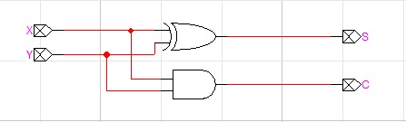
- Label the ports x and y and c and s.
Right click on the port (not the wire), and select "Name...".
- Save the Circuit.
If you end up with an error here, double check that you labeled your ports and not the wires.
Part 2: Creating the Device
Now, we need to create a device out of this circuit.
- Choose File > New and select "Device Symbol"
- Next, select Options > Subcircuit and Part Type... The following dialog box will be displayed:
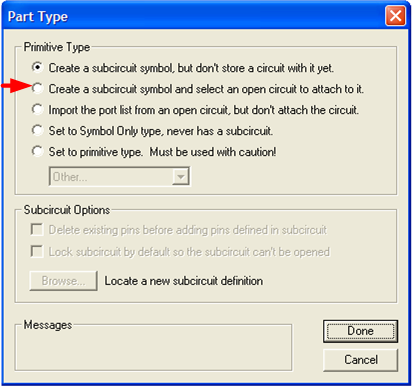
- Select "Create a subcircuit symbol and select an open circuit to attach to it."
- Another dialog will pop up. Click on the circuit that you just created.
- Click on Done. The only thing that has happened is that you have Pin 's on the left hand side.
- Next, select Options > Auto Create Symbol... The following dialog box will be displayed:
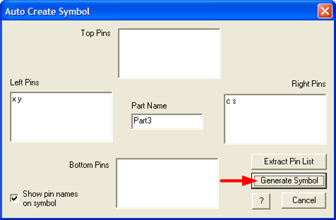
- Click on the "Generate Symbol" button.
You now have a device!
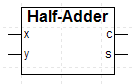
- Double click on the name of the device ("Part#"). A dialog will pop up; replace the Text ("Part#") with "Half-Adder"
- Resize the box to fit the name.
- If you would like, drag the pins around so that the ordering is as you like.
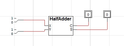
The resulting device will look something like this:
Part 3: Saving to a Library
Once you have the device created, you will have to save it to a library so that you can create circuits that contain this device.
Note: You can use the same library to store the different devices that you
will create in the lab exercise (in other words, steps 1 and 2 below only
need to be done once for this lab)
- First, create a library. Choose File > Libraries > New Lib...
- Save the library as "adderlab" to your I: drive (the library will have a .clf extension).
- Then, save the part to the library. Choose File > Save As... The dialog box is show below
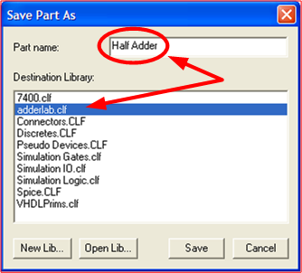
- Change the following:
- Part name: Half Adder
- Destination Library: adderlab.clf
- Click on the Save button
- Now, test it!
- Create a new circuit
- Look under adderlab Library (on the right hand side) for your Half Adder
- Drag the Half Adder onto the workspace
- Connect Binary Switches and Binary Probes to test the truth table
If something is not working how you expect it, you can always double click on the Half Adder Device on the workspace and it will take you to the underlying circuit.
Full-Adder
You can now try and use two half-adders to create a full adder. Again, we will break the problem into steps:
1. State the Problem:
2. Assign Variables:
- Inputs: 3 bits (x, y and ci)
- Outputs: 2 bits (s and ci+1)
3. Construct the Function Table:
Fill in the truth table with what you think ci+1 and s should be. A few have already been filled in for you.
Input |
|
Output |
x |
y |
ci |
|
ci+1 |
s |
0 |
0 |
0 |
|
|
|
0 |
0 |
1 |
|
|
|
0 |
1 |
0 |
|
|
|
0 |
1 |
1 |
|
|
|
1 |
0 |
0 |
|
|
|
1 |
0 |
1 |
|
1 |
0 |
1 |
1 |
0 |
|
|
|
1 |
1 |
1 |
|
1 |
1 |
4. Simplify
Here, you could use a Karnaugh Map to reduce the problem and draw the circuit. We want to use two half-adders and some additional gate.
Again, just looking at the truth table, we can see that one of the outputs (ci+1 or s) uses XOR gates. How do I know that? XOR enables you to do a parity check. The idea is: when there is an odd number of 1 bits, the XOR results are 1, otherwise they are 0. For instance
1 XOR 1 XOR 0 = 0 (Notice that there are two 1-bits)
1 XOR 0 XOR 0 = 1 (Notice that there is one 1-bit)
We can hook up inputs into two half adders devices to get the results of the two XORS. How do we do that?
What's left? Figure out what's coming out of the outputs that aren't from the XOR gate.
What additional gate do we need? You may have to use the Karnaugh map.
Working Later
When you try this project on another machine, you might not find your library in the library list. To access your library, right click on the "parts preview pane" to get the menu shown below:
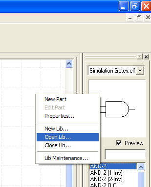
Select "Open Lib..." and navigate to your library.
 Copyright: Department of Computer Science, University of Regina.